
Fault Codes for JCB 220. Inscription on the monitor
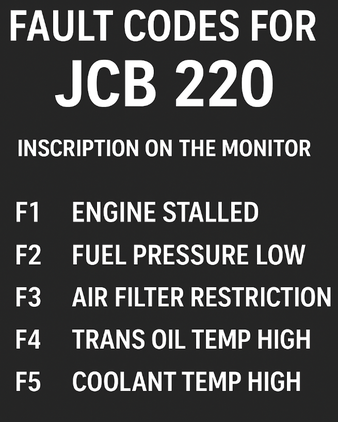
JCB 220 Excavator Error Codes. Displaying Icons on the Monitor. This page provides a decoding of the JCB 220 excavator error codes displayed on the monitor. Detailed descriptions of faults, possible causes of their occurrence and recommendations for their elimination will allow you to quickly diagnose and fix the problem.
JCB codes (hydraulics and electronics)
Error codes / Display on the monitor / Description of the fault
101 CRANK ECU1 does not detect a signal from the crankshaft.
102 FUEL Fuel sensor circuit open
103 AND TMP Engine temperature sensor circuit open.
104 TMP LENGTH Hydraulic fluid temperature sensor circuit open.
105 SET TCH Throttle set position potentiometer circuit open.
106 PT SENS Throttle actual position potentiometer circuit open.
107 OIL SW Oil pressure sensor outputs a pressure signal when the engine is off.
108 FLYWHEEL Cardan gear sensor outputs an engine speed signal when it is off
109 ALL Generator outputs a voltage signal when the engine is off.
110 THR SOL Throttle solenoid circuit is open. Detected only when the engine is off.
111 BOOM SP Boom low speed control circuit is open.
113 MAX FW Maximum flow solenoid circuit is open. For JS200W machines, this error can only be detected
115 BOOM Priority solenoid circuit is open
116 FL PMP Refueling pump output circuit is open.
117 RIG Horn output circuit is open.
118 HYD PMP Hydraulic pump circuit is open. Since the valve is proportional, the error is detected only when the engine is off.
119 SLW LCK Boom lock solenoid circuit is open.
120 LONG WAY Hydraulic fan output circuit open. Detected only when engine is off
121 SLW BRK Boom release solenoid circuit open
122 SLW ST Boom shutoff solenoid circuit open.
127 TL CHNG Travel speed change solenoid circuit open.
128 WASHING MACHINE Washer motor circuit open.
129 BULLDOZER Blade solenoid circuit open.
130 GRB CW Grab clockwise solenoid circuit open.
131 GRB CCW Grab counterclockwise solenoid circuit open.
132 LW FLOW Low flow solenoid circuit open.
133 ISOL Waterproof solenoid circuit open.
135 2 STAGE Stage 2 safety solenoid circuit open.
136 QK HTCH Quick clutch solenoid circuit open.
138 HAMMER Hammer solenoid circuit open.
139 PAD Hard/soft pad solenoid circuit open.
142 ENG SD Engine shutdown output circuit open.
143 GLW PLG Glow plug output circuit open.
156 TL FLW3 Flow solenoid valve circuit 3 open.
157 TL FLW2 Flow solenoid valve circuit 2 open.
158 GR CHNG M2 or gear shift solenoid valve circuit open.
159 VUS LT Brake lamp output circuit open.
160 AXLE LK Bridge lock solenoid valve circuit open.
161 ROLL Stabilizer lift solenoid valve circuit open.
162 ROLL OUT Stabilizer lower solenoid valve circuit open.
163 STAB LH Left stabilizer solenoid valve circuit open.
164 STAB RH Right stabilizer solenoid valve circuit open.
165 CRUISE Cruise control solenoid valve circuit open.
166 DIG ISL Cutting edge isolator solenoid valve circuit open.
167 PDC M1 or parking brake solenoid valve circuit open.
168 DRV ISL Drive isolator solenoid valve circuit open.
202 FUEL Fuel level sensor circuit short.
203 I TMP Engine temperature sensor circuit short.
204 TMP LENGTH Hydraulic fluid temperature sensor circuit short.
205 SET TCH Short circuit in the throttle setpoint potentiometer circuit.
206 PT SENS Short circuit in the throttle actual position potentiometer circuit.
210 THR SOL Short circuit in the throttle solenoid valve circuit. Detected only when the engine is off.
211 BOOM SP Short circuit in the low speed needle adjustment circuit.
212 INT LT Short circuit in the interior lighting circuit.
213 MAX FW Short circuit in the maximum flow solenoid valve circuit. For JS200W machines, this error can only be detected when the engine is off, since these machines have a proportional valve.
214 BEACON Short circuit in the beacon circuit.
215 BOOM PR Short circuit in the priority solenoid valve circuit.
216 FL PMP Short circuit in the refueling pump solenoid valve circuit.
217 HORN Short circuit in the horn circuit.
218 HYD PMP Short circuit in the hydraulic pump circuit. Since the valve is proportional, the error is only detected when the engine is off.
218 HYD PMP Short circuit in the hydraulic pump circuit. Since the valve is proportional, the error is only detected when the engine is off.
219 SLW LCK Short circuit in the boom lock solenoid valve circuit. 220 HYD FAN Short circuit in the hydraulic fan solenoid valve circuit
220 LONG WAY Short circuit in the hydraulic fan solenoid valve circuit. Detected only when the engine is off.
221 SLW BRK Short circuit in the boom unlock solenoid valve circuit.
222 SLW ST Short circuit in the boom shut-off solenoid valve circuit.
223 LW WIPR Short circuit in the lower wiper circuit.
224 Wiper Short circuit in the wiper circuit.
225 LH CAB LT Short circuit in the arrow work light circuit.
226 RH CAB LT Short circuit in the tool box work light circuit.
227 TL CHNG Short circuit in the speed changeover solenoid valve circuit.
228 WASHING MACHINE Short circuit in the washer motor circuit.
229 BULLDOZER Short circuit in the blade solenoid valve circuit.
230 GRB CW Short circuit in the grab clockwise rotation solenoid valve circuit.
231 GRB CCW Short circuit in the grab counterclockwise rotation solenoid valve circuit.
232 LW FLOW Short circuit in the low flow solenoid valve circuit.
233 ISOL Short circuit in the isolator solenoid valve circuit.
234 EMG STP Short circuit in the emergency stop solenoid valve circuit.
235 2 STAGE Short circuit in the safety solenoid valve circuit of stage 2.
236 QK HTCH Short circuit in the quick clutch solenoid valve circuit.
237 TL ALRM Short circuit in the touch-off alarm circuit.
238 HAMMER Short circuit in the hammer solenoid valve circuit.
239 PAD Short circuit in the hard/soft pad solenoid valve circuit.
240 BOOM LT Short circuit in the boom work light circuit.
241 ENG SD Short circuit in the engine stop solenoid valve circuit.
242 ENG SD Short circuit in the engine stop solenoid valve circuit.
243 GLW PLG Short circuit in the glow plug circuit.
244 CNT LT Short circuit in the counterbalance work light circuit.
244 LH IN Short circuit in the left turn indicator circuit.
245 LH IN Short circuit in the left turn indicator circuit.
246 LEFT SIDE Short circuit in the left side light circuit.
247 LH ZUB Short circuit in the left fog light circuit.
248 LH MAIN Short circuit in the left high beam headlight circuit.
249 LH DIP Short circuit in the left low beam headlight circuit.
250 RH IND Short circuit in the right turn indicator circuit.
251 RIGHT SIDE Short circuit in the right side light circuit.
252 RH ZUB Short circuit in the right fog light circuit.
253 HRM MAIN Short circuit in the right high beam headlight circuit.
254 RH DIP Short circuit in the right low beam headlight circuit.
255 HZD LED Short circuit in the hazard LED circuit.
256 TL FLW3 Short circuit in the flow rate solenoid valve circuit 3 movement.
257 TL FLW2 Short circuit in the flow rate solenoid valve circuit 2 movement.
258 GR CHNG Short circuit in the M2 solenoid valve circuit or gear shift.
259 VUS LT Short circuit in the brake lamp output circuit.
260 AXLE LK Short circuit in the bridge lock solenoid valve circuit.
261 ROLL Short circuit in the stabilizer lift solenoid valve circuit.
262 ROLL OFF Short circuit in the stabilizer lower solenoid valve circuit.
263 STAB LH Short circuit in the left stabilizer solenoid valve circuit.
264 STAB RH Short circuit in the right stabilizer solenoid valve circuit.
265 CRUISE Short circuit in the cruise control solenoid valve circuit.
266 DIG ISL Short circuit in the cutting edge insulator solenoid valve circuit.
267 PRK BK Short circuit in the M1 or parking brake solenoid valve circuit.
268 DRV ISL Short circuit in the drive isolator solenoid valve circuit.
300 EC1 CAN ECU1 communication with the CAN bus is interrupted.
301 ECW CAN ECUW communication with the CAN bus is interrupted.
302 THRT CAL The difference between the maximum and minimum calibration points for the throttle dial potentiometer is less than 100 A/D points.
304 THRT CAL The position of the dial potentiometer has changed by more than 10%, but the engine continues to run at idle. This condition must last at least 15 seconds to be recorded. This error does not exist on machines with EEC (Electronic Engine Controller).
JCB Engine Error Codes (Isuzu 4HK, 6HK)
DTC Error Codes DTC Description (Errors)
P0016 Mismatch between Crankshaft and Camshaft Position Sensors
P0045 Mismatch between Crankshaft and Camshaft Position Sensors
P0079 Low signal level in the exhaust flap solenoid valve circuit
P0080 High signal level in the exhaust flap solenoid valve circuit
P0087 Low pressure in the fuel rail/fuel supply system
P0088 High pressure in the fuel rail/fuel supply system (first stage)
P0089 Fuel pressure regulator malfunction
P0091 Low signal level in the fuel pressure regulator circuit
P0092 High signal level in the fuel pressure regulator circuit
P0093 Leak in the supply system fuel
P0101 Incorrect signal or malfunction of the mass air flow sensor circuit
P0102 Low signal level at the input of the mass air flow sensor
P0103 High signal level at the input of the mass air flow sensor
P0107 Low signal level at the input of the absolute pressure sensor located in the intake manifold
P0108 High signal level at the input of the absolute pressure sensor located in the intake manifold
P0112 Low signal level in the circuit of the air temperature sensor at the intake manifold
P0113 High signal level in the circuit of the air temperature sensor at the intake manifold
P0116 Incorrect signal or malfunction of the circuit of the coolant temperature sensor
P0117 Low signal level in the circuit of the coolant temperature sensor
P0118 High signal level in the circuit of the coolant temperature sensor
P0122 Low signal level in the circuit of the throttle position sensor throttle
P0123 Throttle Position Sensor Circuit High
P0182 Throttle Position Potentiometer Circuit Short.
P0183 Low signal level in the fuel temperature sensor circuit
P0192 Low signal level in the fuel pressure sensor circuit
P0193 High signal level in the fuel pressure sensor circuit
P0201 Open circuit in the injector circuit of the first cylinder
P0202 Open circuit in the injector circuit of the second cylinder
P0203 Open circuit in the injector circuit of the third cylinder
P0204 Open circuit in the injector circuit of the fourth cylinder
P0217 Excess coolant temperature
P0219 Engine crankshaft speed conversion
P0234 Excess boost pressure
P0299 Insufficient boost pressure
P0335 Malfunction in the crankshaft position sensor circuit
P0336 Incorrect signal or malfunction of the crankshaft position sensor circuit
P0340 Malfunction camshaft position sensor circuit
P0341 Incorrect signal or malfunction of the camshaft position sensor circuit
P0380 Malfunction in the glow plug circuit
P0381 Malfunction in the preheating system control lamp circuit
P0401 Insufficient amount of recirculated gases
P0404 Incorrect signal or malfunction of the EGR system control circuit.
P0409 EGR valve position sensor circuit malfunction
P0426 Incorrect signal or malfunction in the exhaust gas temperature sensor #1 circuit
P0427 Low signal level in the exhaust gas temperature sensor #1 circuit
P0428 High signal level in the exhaust gas temperature sensor #1 circuit
P042B Incorrect signal or malfunction in the exhaust gas temperature sensor #2 circuit
P042C Low signal level in the exhaust gas temperature sensor #2 circuit
P042D High signal level in the exhaust gas temperature sensor #2 circuit
P0477 Low signal level in the exhaust flap control circuit
P0478 High signal level in the exhaust gas pressure control valve circuit
P0487 Exhaust gas recirculation (EGR) system, position control flaps - electrical circuit malfunction
P0500 Speed sensor malfunction
P0502 Hammer solenoid valve circuit short circuit.
P0503 Low level at the speed sensor input
P0560 Incorrect voltage in the on-board network
P0563 High voltage in the on-board network
P0601 Checksum error of the internal RAM of the control unit
P0602 Control unit programming error
P0604 Control unit internal RAM error
P0606 ECM processor malfunction
P060B Malfunction in the internal analog-to-digital converter circuit of the control unit
P0633 Immobilizer not programmed
P0638 Incorrect signal or malfunction in the throttle actuator control circuit
P0641 Malfunction in the reference voltage circuit of sensor No. 1
P0650 Malfunction in the control circuit of the “Check Engine” control lamp
P0651 Malfunction in the reference voltage circuit of sensor No. 2
P0685 Open in the control circuit of the ECM power supply relay
P0687 High signal level in the control circuit of the ECM power supply relay
P0697 Malfunction of the reference voltage circuit of the sensor No. 3
P1093 Insufficient fuel pressure.
P1261 Positive voltage of the control circuits of the injectors of group No. 1
P1262 Positive voltage of the injector control circuits of group No. 2
P1404 Incorrect position of the ESC system valve (closed position error)
P1455 Excessive content of solid particles in the particulate filter
P1471 Insufficient degree of regeneration of the particulate filter
P161B Short circuit of the stabilizer lift solenoid valve circuit.
P1621 Incorrect immobilizer response signal
P1664 Service indicator control circuit
P1669 Diesel particulate filter warning lamp control circuit
P2122 Low signal level at the input of the accelerator pedal position sensor No. 1
P2123 High signal level at the input of the accelerator pedal position sensor No. 1
P2127 Low signal level at the input of the accelerator pedal position sensor No. 2
P2128 High signal level at the input of the accelerator pedal position sensor No. 2
P2138 Inconsistency of the readings of the accelerator pedal position sensors No. 1 and No. 2
P2146 Voltage supply circuit for injectors of group No. 1
P2149 Voltage supply circuit for injectors of group No. 2
P2227 Incorrect signal or malfunction of the atmospheric pressure sensor circuit
P2228 Low signal level of the circuit atmospheric pressure sensor
P2229 High signal level of the atmospheric pressure sensor circuit
P242F Clogging of the particulate filter
P2452 Malfunction in the differential pressure gauge circuit
P2453 Incorrect signal or malfunction of the differential pressure gauge circuit
P2454 Low signal level in the differential pressure gauge circuit
P2455 High signal level in the differential pressure gauge circuit
P2456 Incorrect initialization of the differential pressure gauge
P2458 Exceeding the duration of the differential pressure gauge regeneration
P253A Malfunction of the power take-off sensor circuit
P256A Malfunction of the idle speed regulator circuit
U0073 Disconnection of the control unit communication bus
U0101 Open connection with the transmission control unit (TSM)
U0110 Open circuit with variable geometry turbocharger control unit
U0167 Open circuit with immobilizer control unit
JCB 220 Typical Error Codes and Causes
E-001 / Low engine oil pressure
Causes: worn oil pump, oil leak, clogged filter, low oil level.
E-002 / High coolant temperature
Causes: thermostat failure, fan failure, low coolant level, dirty radiator.
E-010 / Fuel system failure
Causes: clogged fuel filter, fuel injection pump failure, air in the system.
E-020 / Hydraulic pressure sensor failure
Causes: sensor damage, broken wire, hydraulic fluid leak.
E-030 / Hydraulic system overheating
Causes: low hydraulic oil level, clogged filter, equipment overload.
E-050 / Boom or bucket position sensor failure
Causes: sensor failure, broken cable, damaged connector.
E-100 / Control system (ECU) failure
Causes: software failure, poor connector connection, control unit damage.
E-200 / Generator or battery error
Causes: alternator belt break, poor contact of battery terminals, worn-out battery.
E-300 / CAN bus error
Causes: wiring problems, connector oxidation, electronic module failure.
E-400 / AdBlue (SCR) system problems (for Euro-4/5 models)
Causes: low AdBlue level, clogged dosing module, NOx sensor failure.